Daily Work
Here you can see the work we have done on a daily basis and the different problems we have encountered.
9/3/2022
Our teacher gave us the material on the first day to try to set up the circuit. You can see all the material in this link.
10/3/2022
Before trying to make the code we looked in some books how to make the SOS and look for the structure of the microchip, i.e. the analogue inputs and outputs.

14/3/2022
We didn't have much idea of how to create the code, and the only thing we managed to do was to connect the port, but unfortunately it didn't detect it and it wasn't the fault of the USB, as we tried it with other USB cables from our colleagues, but we had to install several ESP-32 libraries, which in the end didn't help us at all.
18/3/2022
We looked at the official 'Espressif' website for more information about the microchip. And we installed the drivers from the website itself but still no solution.
24/3/2022
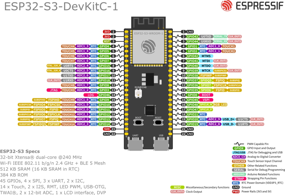
There are two ways to achieve this: 1- "Circuit Python" is an interpreted Python language and has a serial REPL. 2- "Esp-IDF Visual Code" has a "compiled C" language. We also installed "MakeCode for Adafruit" from the Microsoft shop. Install CircuitPython 7.2.3 for ESP32-S3-DevKitC-1-N8R8 in .uf2 format. Press and hold the "boot" button first and then "reset" for a few seconds to enter bootloader mode. We go to "this computer" and look in "devices and units" to see if we see the microcontroller. In this case we have not found it, so we will have to find a solution
28/3/2022
Today we will use another different microcontroller, simpler than the previous one and to know how this microcontroller works, it is called ESP-WROOM-32(put image) which contains WiFi and Bluetooth. We have had a problem, it does not detect the port in any computer.

30/3/2022
We still have the same problem, the computer does not detect the port. In "Device Manager" we activated the "view hidden devices" mode in the "View" tab. Even so, it still does not detect the device, we have tried changing the cable, but nothing has changed, the "error 045" is still displayed. We have restarted the microcontroller from scratch, and now it doesn't even install correctly. We have tried to install the files from the drivers folder manually, but it doesn't work.
31/3/2022
We have managed to turn on the Arduino Uno R3 that connects to the port and finally we have managed to assemble the circuit and illuminate the LED. Now we use the Tinkercad App (https://www.tinkercad.com/), from here we create the code and simulate the circuit. While we create the code we simulate and try to write SOS in morse code. Once we have it we copy it to the Arduino editor (Arduino IDE).

4/4/2022
We had searched for information about the structure of the Arduino and also managed to create the first code using only simple instructions. And therefore the flashing and the SOS.

5/4/2022
We managed to create the second code using only variables and parameters without functions and to understand the code. And therefore the flashing and the SOS reflected on the LED differently.
6/4/2022
Try to make the poster (thumbnail or default image) with GIMP using a code from open drive that includes the control command where you can see the elapsed time of the video, to pause it, etc. This command is also very powerful because it is HTML5, and finally try to make a simulation with tinkercad.

7/4/2022
We soldered the loudspeakers with tin and the soldering iron so that we could use it later.
Easter Holidays
19/4/2022 → 21/4/2022
We created the 4 remaining codes with Arduino IDE, 4 of them with LEDs and another one with 1 LED and a speaker, and we were able to understand the codes. We also took the opportunity to record some videos, all of this you can see in each section of the simulation section.
25/4/2022 → 2/5/2022
We did the mythical pong game, to know how to use classes, conditionals, the syntax of the dot, variables, etc. We created different pongs, 4 to be precise, all of them are different and each one shows a different thing. To create all this videogame we need an index.html , Sketch.js, Paddle.js, Score.js, Ball.js, style.css
3/5/2022
Once the pong game was over, we went back to the microcontrollers. This time using processing, which is basically a derivative of java and C++ that is often used for beginners. Also, it is widely used to create interactive things. Processing is much more complete than arduino, that is to say it has many more options, because Arduino is a derivative of processing. Once you have downloaded processing, you have to look for the Arduino libraries and insert them.
4/5/2022
To use processing we will need to use the ESP32-S3-DevKit board, as it has Bluetooth and WiFi, and is therefore more powerful and complete than the Arduino. In other words, it was our nightmare again, because in the past it didn't work for us. And at first it didn't work for us again.
5/5/2022
We were trying for an hour to get the microcontroller detected on the computer (unlike in the past). But unfortunately it remained undetected and we assumed that it was in beta phase.
9/5/2022
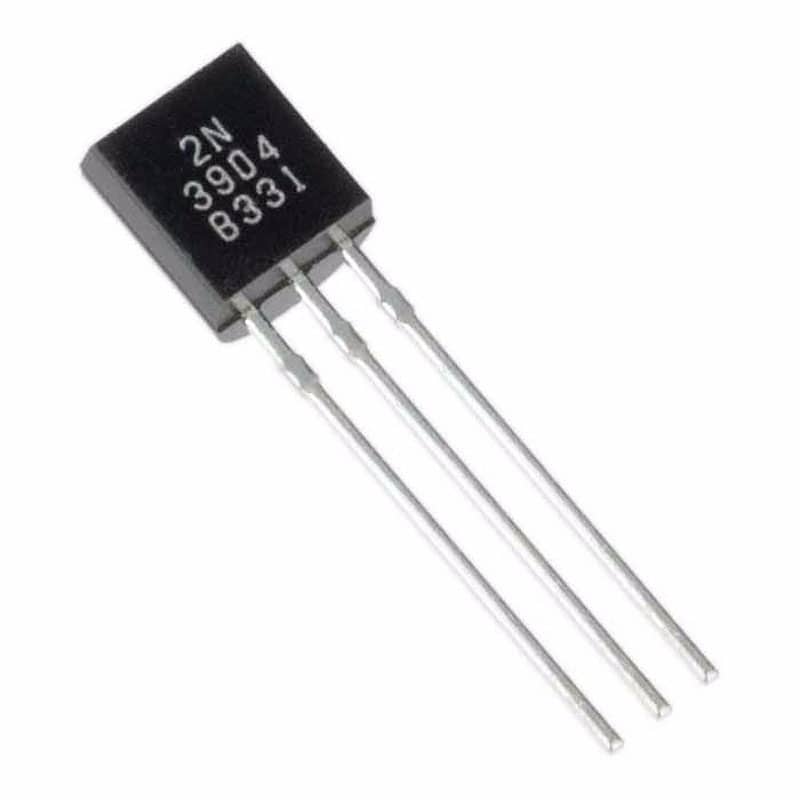
In the next class we forgot about processing, as we could not use it. And our teacher explained and gave us different materials to make our own project: Transistors, which serve as a current amplifier, like a switch.

There are different types of transistors depending on the PN junction.
Diodes serve to give only one direction to the current, they are also PN junction and are made of semiconductors.

Ceramic capacitor, no polarity, units in nanofarads.
Electrolitic capacitor, used to accumulate electric charge and then release it. Its unit is in microfarads, and has polarity.
555: It can be used as a timer and has several internal transistors and diodes, it is a potentiometer or variable resistor.
745N74L547N: We join many transistors and we obtain microxips. SSI (Small Size Integrations)=100transistors MSI(Medium Size Integrations)=1000transistors LSI(Large Size Integrations)=10000transistors
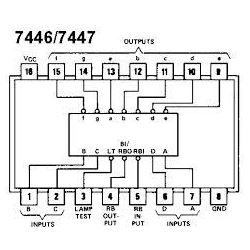
7447: specialised microxip for 7-segment displays.

10/5/2022
As it was a strike day("huelga"), we took advantage of it and continued with COSCE project to make both the scientific poster and the scripts for the videos.
.png)
11/5/2022→ 2/6/2022
Let's start with our own project, to be able to change the colour of an LED-RGB with three LDRs with the map function, and we also did it with a flex sensor and a pressure sensor. And so we were able to create a great colour combination. We didn't have any problems in making the code or the circuit.
When we finished this project so soon we thought about making it with a remote control to do various actions. The first problem was that we were looking on the internet and we were told that we needed a resistor of more than 22.000 Ohms, and it was not easy to find it, but later we discovered that our remote control receiver already comes with a bigger resistor.
Another big problem, but so simple, is that the remote control was not transmitting ultraviolet rays (this can be seen with the mobile camera, the eye can't reach it) and it was because there was a label on the remote control battery that we had to remove. Later, we had to find out the hexadecimal code of each button on the remote control and that's it, now we will continue working.
- 1 → FFA25D
- 2 → FF629D
- 3 → FFE21D
- 4 → FF22DDD
- 5 → FF02FD
- 6 → FFC23D
- 7 → FFE01F
- 8 → FFA857
- 9 → FF906F
- 0 → FF9867
- * → FF6897
- # → FFB04F
- Up Arrow → FF18E7
- Down Arrow → FF4AB5
- Right Arrow → FF5AA5
- Left Arrow → FF10EF
- OK → FF38C7